
Diagram & spare parts – KF50
Air Brad Nailer · 76 parts
Exploded diagram
Click the image to zoom.
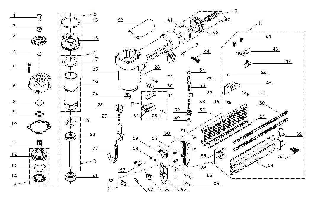
Spare parts list
Tick the parts you need, then press the chat button below.
| Select | No. | Part code | Part name | Remark |
|---|---|---|---|---|
| 1 | 30009001685 | 0Hex Socket Countersunk Head Screw M4×12 | ||
| 2 | 30009001662 | Exhaust Valve Cap Sleeve | ||
| 3 | 30009000474 | Exhaust Valve Cap | ||
| 4 | 30009001663 | O Ring 7.8×1.9 | ||
| 5 | 30021100154 | Hex Socket Cap Screw M5×35 | ||
| 6 | 30009000475 | Cylinder Cover | ||
| 7 | 30021300017 | Hex Lock Nut M5 With Non-Metallic Insert, Type I Style | ||
| 8 | 30009000476 | Control Washer | ||
| 9 | 30009000477 | O Ring 13.6×2.4 | ||
| 10 | 30009000478 | Seal | ||
| 11 | 30009000479 | Compression Spring | ||
| 12 | 30009000480 | Balance Valve | ||
| 13 | 30009000429 | O Ring 31.3×2.5 | ||
| 14 | 30009001664 | Balance Valve Seal | ||
| 15 | 30009000482 | O Ring 43.3×3.5 | ||
| 16 | 30009000483 | Sleeve Retainer | ||
| 17 | 30009000484 | O Ring 31.5×1.8 | ||
| 18 | 30009000485 | Cylinder | ||
| 19 | 30009000486 | O Ring 22.3×3 | ||
| 20 | 30009001665 | Piston Assembly | ||
| 21 | 30019901269 | Buffer | ||
| 22 | 30009000489 | Leather Cover | ||
| 23 | 30009000490 | Main Housing (DCA) | ||
| 24 | 30009000493 | Seal | ||
| 25 | 30009000494 | Bracket | ||
| 26 | 30009000495 | Compression Spring | ||
| 27 | 30009000497 | Safety Rack Assembly | ||
| 28 | 30009000443 | O Ring 1.2×1.9 | ||
| 29 | 30009000498 | Pin 3×26 | ||
| 30 | 30009000499 | Stretch Pin3×26 | ||
| 31 | 30009000500 | Insurance Trigger Switch | ||
| 32 | 30009000501 | Trigger Switch | ||
| 34 | 30009000502 | Sealing Gasket12.5×8×1.5 | ||
| 35 | 30009000503 | Valve Base | ||
| 36 | 30009000504 | Compression Spring | ||
| 37 | 30009000505 | O Ring 2.2×1.5 | ||
| 38 | 30009000506 | Valve Lever | ||
| 39 | 30009000507 | Socket | ||
| 40 | 30009000444 | O Ring 11.2×1.9 | ||
| 41 | 30009000491 | O Ring 34×3.5 | ||
| 42 | 30029900382 | Connector | ||
| 43 | 30009000492 | End Cap | ||
| 44 | 30021100319 | Hex Socket Head Screw M5X20 | ||
| 46 | 30009000508 | Positioning Handle | ||
| 47 | 30009000509 | Positioning Handle Torsion Spring | ||
| 48 | 30009000510 | Bracket | ||
| 49 | 30009000511 | Pin Shaft 3×13.5 | ||
| 50 | 30009000516 | Compression Spring | ||
| 51 | 30009000513 | Spacer | ||
| 52 | 30009000514 | Lock Buckle | ||
| 54 | 30009000515 | Activity Cartridge | ||
| 56 | 30009000518 | Top | ||
| 57 | 30009001667 | Hex Socket Head Screw M5×22 | ||
| 58 | 30009000449 | Spring Washer 5 | ||
| 59 | 30009000521 | Baffle | ||
| 60 | 30009000520 | Nail Head | ||
| 61 | 30009000519 | Lock Pin1.5×15 | ||
| 62 | 30009000512 | Fixed Cartridge | ||
| 63 | 30009000522 | Shaft Pin 3×18 | ||
| 64 | 30009000448 | Shaft Pin 3×14.8 | ||
| 65 | 30009000523 | Motor Housing Cover | ||
| 66 | 30009000524 | Quick Release Trigger | ||
| 67 | 30009000525 | Quick Release Sleeve | ||
| 68 | 30009000526 | Quick Release Spring | ||
| A | 30009001668 | Balancing Valve Assembly A | Including: 12, 13, 14 | |
| B | 30009001669 | Shrink-Ring Assembly B | Including: 15, 16 | |
| C | 30009001670 | Cylinder Assembly C | Including: 17, 18 | |
| D | 30050900175 | Piston Assembly D | Including: 19, 20 | |
| E | 30009001671 | Inlet Connection Assembly E | Including: 41, 42, 43 | |
| F | 30009001672 | Trigger Assembly F | Including: 31, 32, 33 | |
| G | 30009001673 | Cover Assembly G | Including: 28, 59, 63, 64, 65, 66, 67, 68 | |
| H | 30009001674 | Magazine Assembly H | Including: 28, 45, 46, 47, 48, 49, 50, 51, 52, 53, 54, 56, 60, 61, 62 | |
| T1 | 30009005082 | Housing Assembly (Blue) | Including: 22, 23, 41-43 | |
| T1 | 30209000096 | Housing Assembly (Green) | Including: 22, 23, 41-43 | |
| T1 | 30509000029 | Housing Assembly (Red) | Including: 22, 23, 41-43 | |
| T2 | 30009005083 | Kit | Including: 8-10, 13-15, 17, 19, 21, 24, 34, 37, 40 |
Source: official Spare Parts List (2023.11). Please quote the part code and position number when ordering.