
Diagram & spare parts – KDYJ40
Cordless Hydraulic Cable Cutter · 72 parts
Exploded diagram
Click the image to zoom.
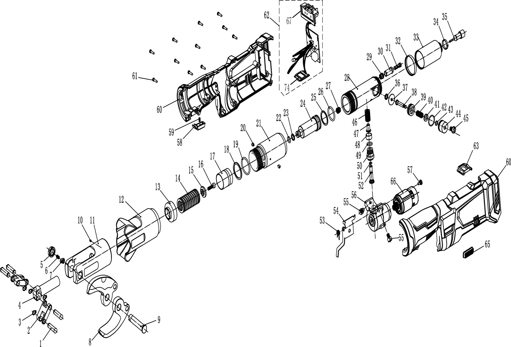
Spare parts list
Tick the parts you need, then press the chat button below.
| Select | No. | Part code | Part name | Remark |
|---|---|---|---|---|
| 1 | 30009008175 | Pin | ||
| 2 | 30009008176 | Connecting Rod | ||
| 3 | 30021600012 | Retaining Ring For Shaft Dia.8 _ | ||
| 4 | 30009008177 | Piston Rod | ||
| 5 | 30009008178 | Pin Nut | ||
| 6 | 30021100096 | Hexagon Socket Set Screws With Flat Point M5×8 | ||
| 7 | 30009008179 | Locking Block | ||
| 8 | 30009008180 | Blade | ||
| 9 | 30009008181 | Pin Crimping Head _ | ||
| 10 | 30021100619 | Hexagon Socket Set Screw With Flat Point M3×5 | ||
| 11 | 30009008182 | Crimping Head | ||
| 12 | 30009008183 | Protective Sleeve | ||
| 13 | 30009008184 | Retainer Ring | ||
| 14 | 30009008185 | Reset Spring | ||
| 15 | 30009008186 | Spring Collar | ||
| 16 | 30021100131 | Hex Socket Cap Screw M5×16 | ||
| 17 | 30009008187 | Piston | ||
| 18 | 30009008188 | Plastic Ring DQ30×25×1.5 | ||
| 19 | 30009008189 | O Ring 23.8×3.1 | ||
| 20 | 30009008136 | Hex Socket Cap Screw M3×3 | ||
| 21 | 30009008190 | Oil Cylinder | ||
| 22 | 30009008137 | O Ring 8×2 | ||
| 23 | 30009008138 | Plastic Ring DQ12×9×1.3 | ||
| 24 | 30009008139 | Piston | ||
| 25 | 30009008140 | Plastic Ring DQ27×22.5×1.2 | ||
| 26 | 30009008141 | O Ring 27.14×2.62 | ||
| 27 | 30009002898 | Check Valve (Outlet) | ||
| 28 | 30009008142 | Cylinder Block | ||
| 29 | 30009002900 | Check Valve (Intlet) | ||
| 30 | 30009002901 | Filter Body | ||
| 31 | 30009002902 | Filter | ||
| 32 | 30009008143 | Slide Bushing | ||
| 33 | 30009008144 | Oil Bag | ||
| 34 | 30009002905 | Cable Tie 4×150 | ||
| 35 | 30009002906 | Faucet | ||
| 36 | 30009002907 | Washer 10×6.7×1 | ||
| 37 | 30009008145 | Relief Valve Base | ||
| 38 | 30009008146 | Relief Valve Needle | ||
| 39 | 30009008147 | Relief Valve Piston | ||
| 40 | 30009008148 | Relief Valve Spring | ||
| 41 | 30009008149 | Copper Washer 6 | ||
| 42 | 30009008150 | O Ring 14×1.5 | ||
| 43 | 30009008151 | O Ring 8.6×1.5 | ||
| 44 | 30009008152 | Relief Valve Spring Base | ||
| 45 | 30009008153 | Pressure Adjusting Screw | ||
| 46 | 30009008154 | Plunger Spring | ||
| 47 | 30009008155 | Guide Pin | ||
| 48 | 30009008156 | Plunger Spring Base | ||
| 49 | 30009008157 | O Ring 12×1.5 | ||
| 50 | 30009008158 | Plunger Guard | ||
| 51 | 30009008159 | O Ring 5.8×1.3 | ||
| 52 | 30009008160 | Plunger | ||
| 53 | 30009008161 | Torsion Spring | ||
| 54 | 30009008162 | Relief Lever | ||
| 55 | 30021100632 | Flat Screw M4×6 | ||
| 56 | 30009008163 | Gearbox Assembly | ||
| 57 | 30009008164 | Relief Valve Screw | ||
| 58 | 30009008165 | Start Button (Red) | ||
| 58 | 30009010236 | Start Button (Black) | ||
| 59 | 30009008166 | Spring For Start Buttton | ||
| 60 | 30009008167 | Motor Housing Assembly (东成) | ||
| 60 | 30009010238 | Motor Housing Assembly (DCA) | ||
| 60 | 30009010239 | Motor Housing Assembly (DCK) | ||
| 60 | 30009010240 | Motor Housing Assembly (DongCheng) | ||
| 61 | 30021200014 | Torx Pan Head Tapping Screw ST2.9×16 | ||
| 62 | 30009008191 | Circuit Board Assembly | ||
| 63 | 30009008169 | Display Panel Case | ||
| 65 | 30009008170 | Relief Valve Button (Red) | ||
| 65 | 30009010237 | Relief Valve Button (Black) | ||
| 66 | 30009008171 | Motor Assembly | ||
| 67 | 30019901498 | Terminal Socket | ||
| 68 | 30009008172 | Display Panel |
Source: official Spare Parts List (2023.11). Please quote the part code and position number when ordering.